[計算例 6] 一定勾配水路への塩水楔の侵入
感潮河川では,潮の干満により河口水位が上下に振動し,これが河川流に影響を及ばす. ここでは,単純な水路を想定し,下流端の水位変動による塩水楔の挙動を計算する.
計算格子の生成
計算格子の作成はNays2dv専用の格子生成ツールを用いる. Figure 95 で[Nays2dv用格子生成ツール]を選択し.[OK]をクリックする.
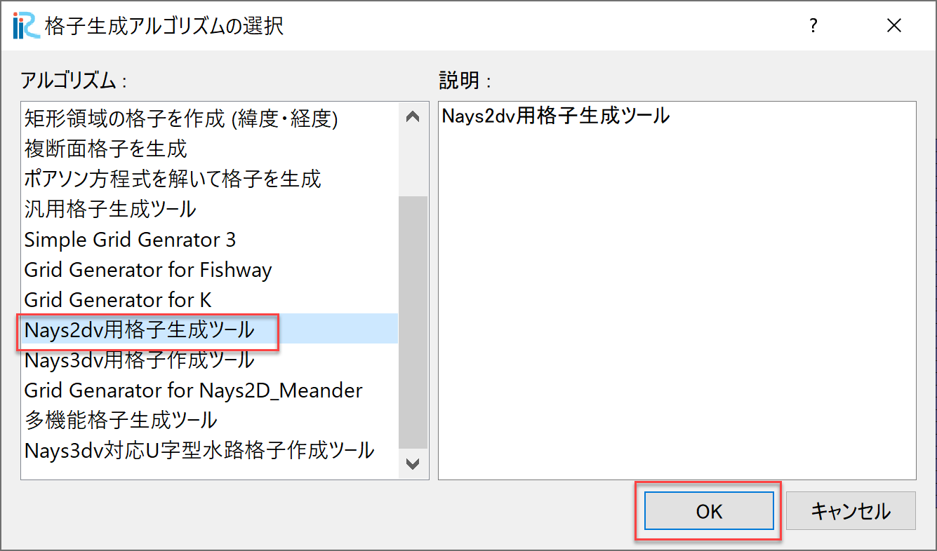
Figure 95 : 格子生成アルゴリズムの選択
「格子生成」ウィンドウが現れるので, Figure 96 の「グループ」「河床形状」 で赤囲いの部分を設定する.これにより一定勾配の水路が設定される.
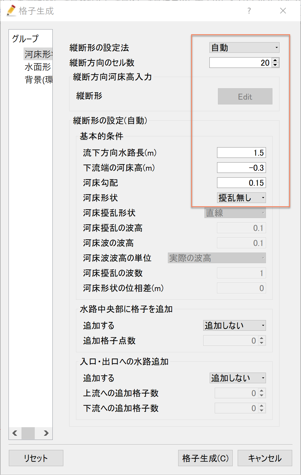
Figure 96 : 格子生成: 河床形状
次に,「グループ」「水面形」を選び. Figure 97 で赤囲いの部分を設定する. これで,初期水面形は水平な条件となる.設定が終わったら[格子生成]をクリックする.
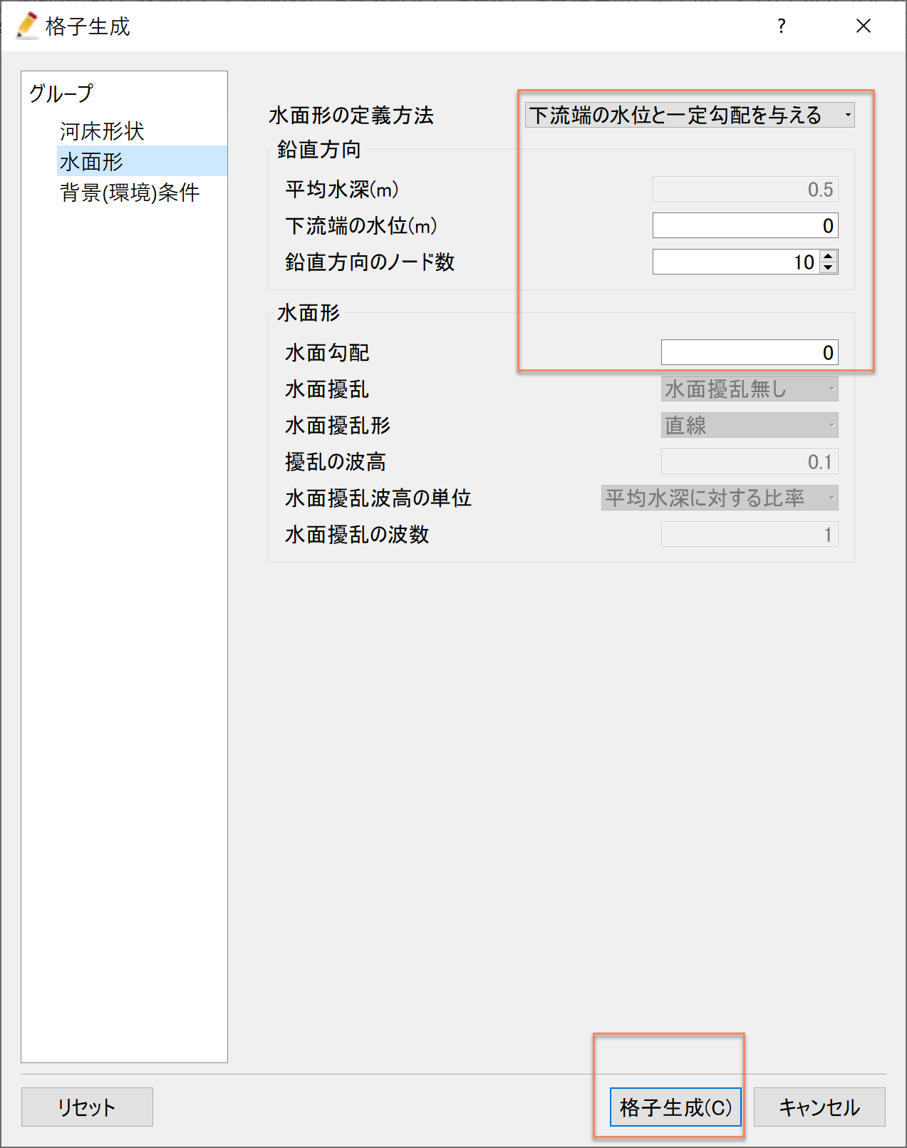
Figure 97 : 格子生成: 水面形
「マッピングを実行しますか?」と聞かれるので[はい(Y)]をクリックする ( Figure 98 ) .
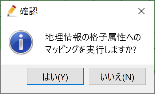
Figure 98 : 格子生成: マッピング
濃度境界条件の設定
下流端において塩水の境界条件を設定する. Figure 99 に示すように,オブジェクトブラウザーで「境界条件設定」にチェックマーク☑を入れて右クリックし, 「濃度境界の追加」を選ぶ.その後.下流端の境界エッジに沿って範囲を指定し,終了時 に「Enter」を打ち込むことにより現れる「境界条件」 ウィンドウ( Figure 100 )で必要な情報を入力し[OK]ボタンを押す.
Figure 99 : 格子生成: 濃度境界の追加
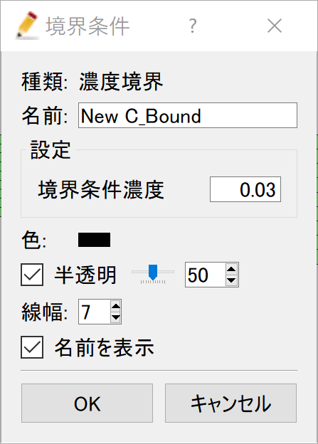
Figure 100 : 格子生成: 濃度境界条件の設定
指定した境界条件を格子情報へマッピングを行う. メニューバーから「格子」「マッピング」「実行」を Figure 101 に示すように 選択し実行する.
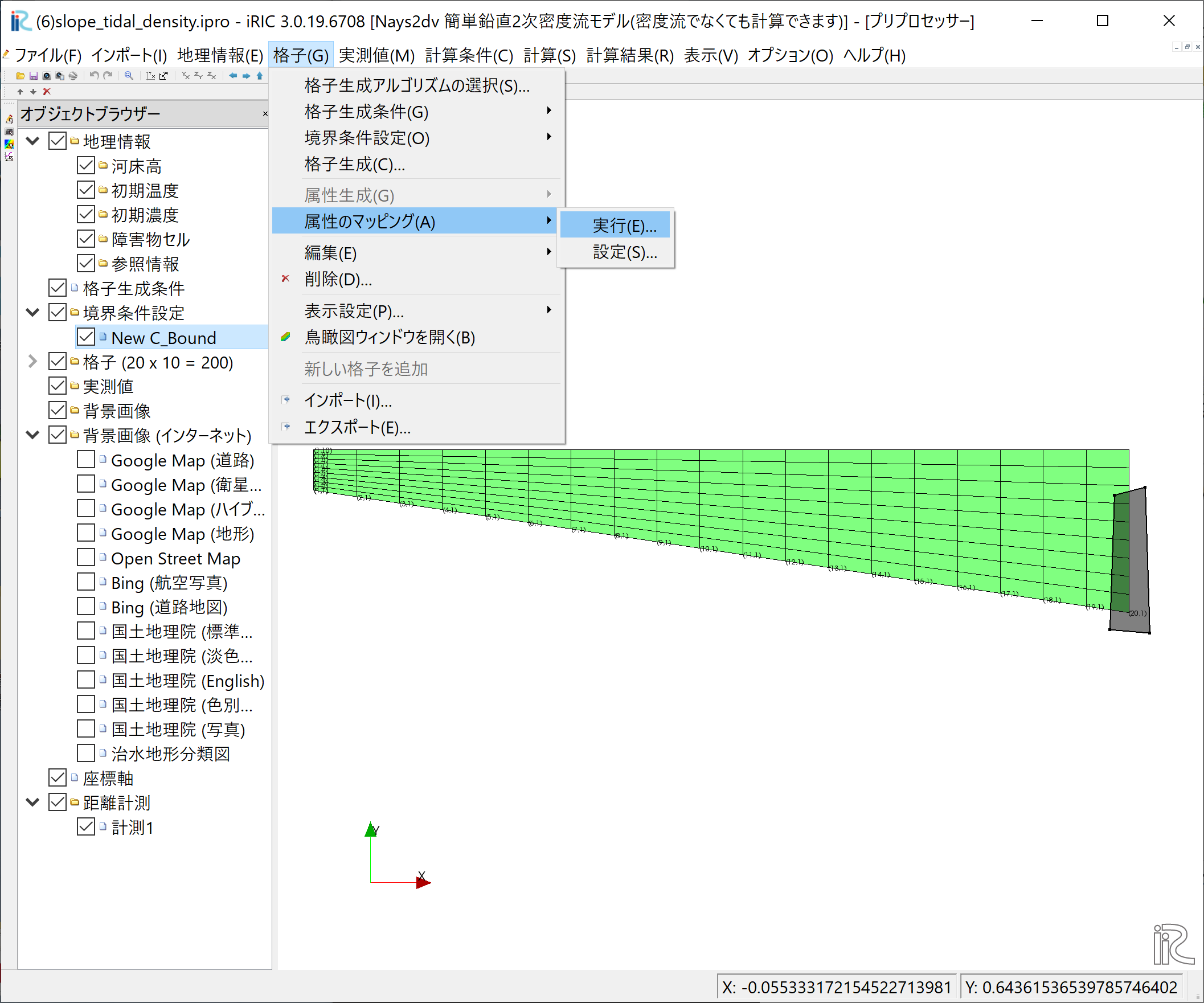
Figure 101 : 格子生成: 濃度境界条件のマッピング(1)
Figure 102 のウィンドウが表示されるので「New C_Bound」に☑マーク を入れて[OK]を押すと.
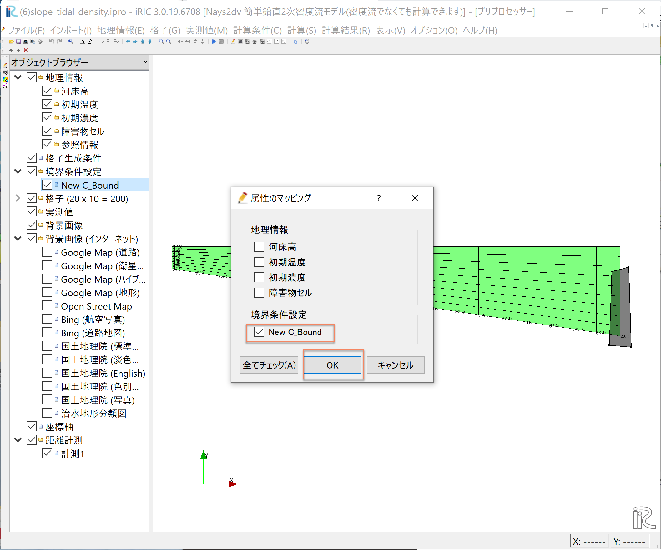
Figure 102 : 格子生成: 濃度境界条件のマッピング(2)
計算条件の設定
メニューバーから[計算条件]→[設定]を選ぶと「計算条件」入力用のウィンドウが表示される Figure 103 「差分計算方式」は「流速の移流項」も「密度の移流項」も[風上差分]を選ぶ.
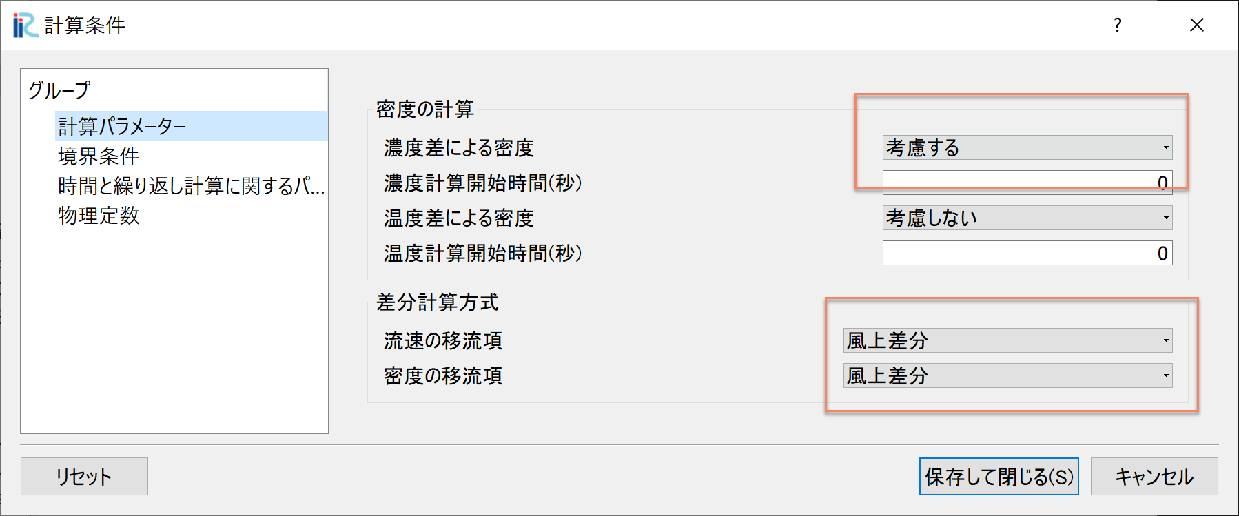
Figure 103 : 計算条件:計算条件
「計算条件」「グループ」「境界条件」を選ぶと Figure 104 が表示されるので, 「上下流の境界条件」は[上下流自由境界], 「上流からの流量供給」は[与えない]を選ぶ.
「下流端の水位は」[サインカーブ振動]とし, Figure 104 に示すパラメータで 与える.
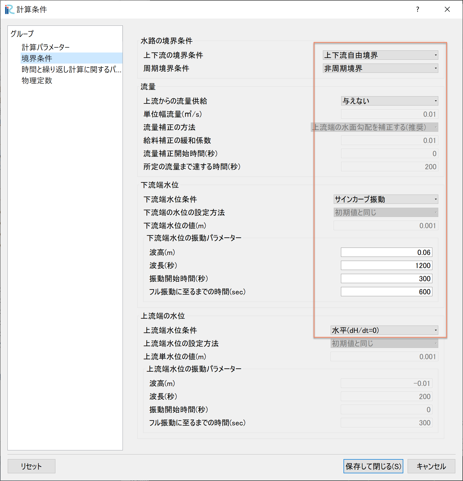
Figure 104 : 計算条件:境界条件
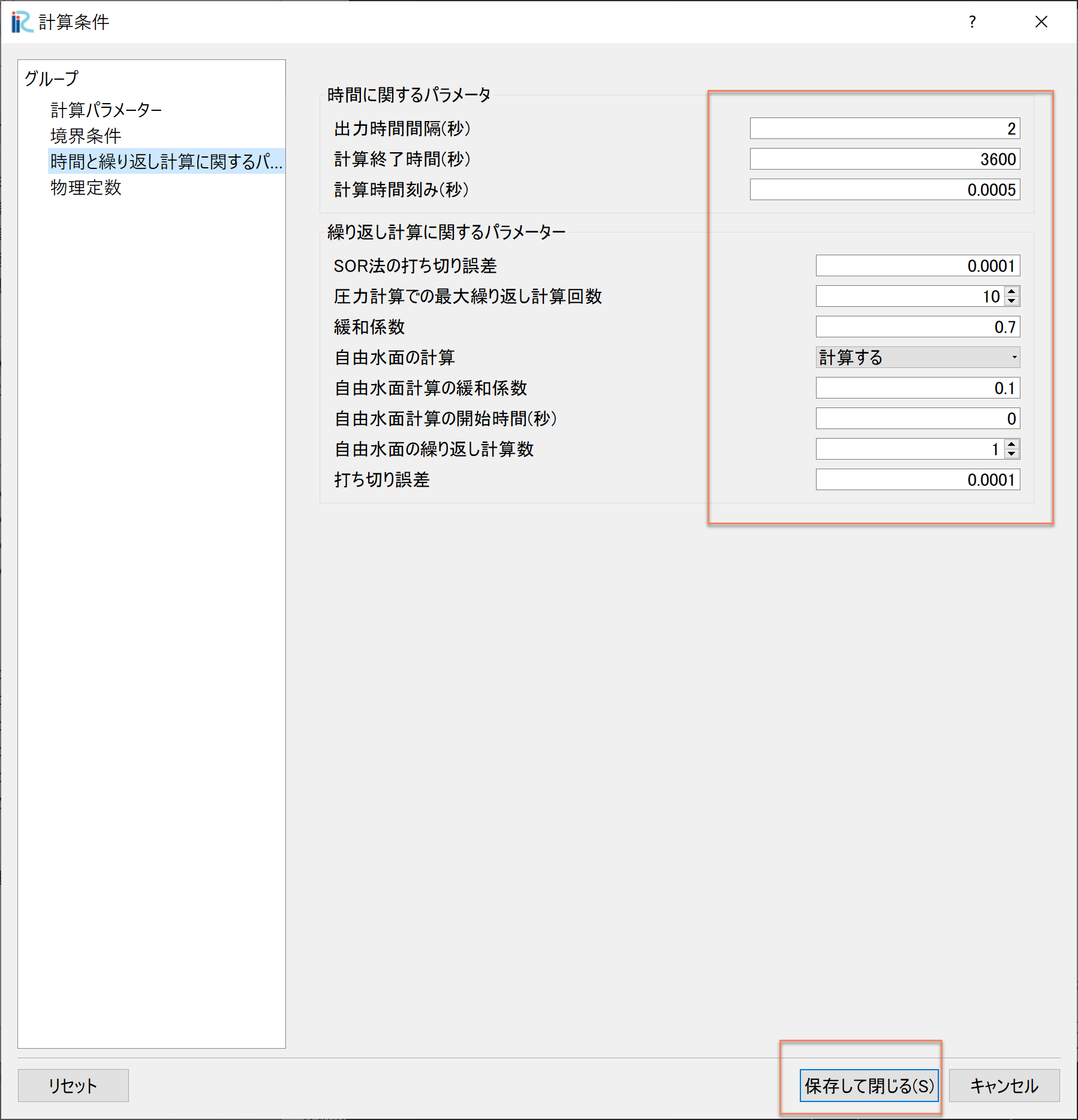
Figure 105 : 計算条件:時間およに繰り返し計算パラメーター
「計算条件」の「時間と繰り返し計算に関するパラメーター」は Figure 105 の赤囲いのように設定すし.設定が終わったら[保存して終了」をクリックする.
計算の実行
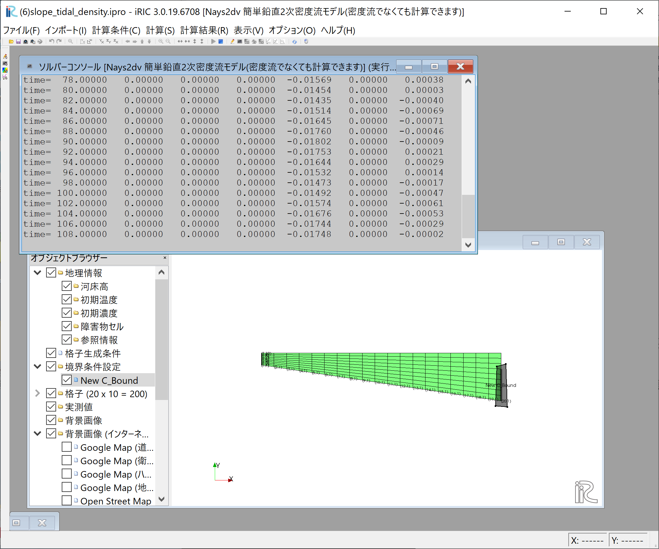
Figure 106 :計算実行中の画面
[計算]→[実行]を指定すると,Figure 106 のような画面が現れ計算が始まる.
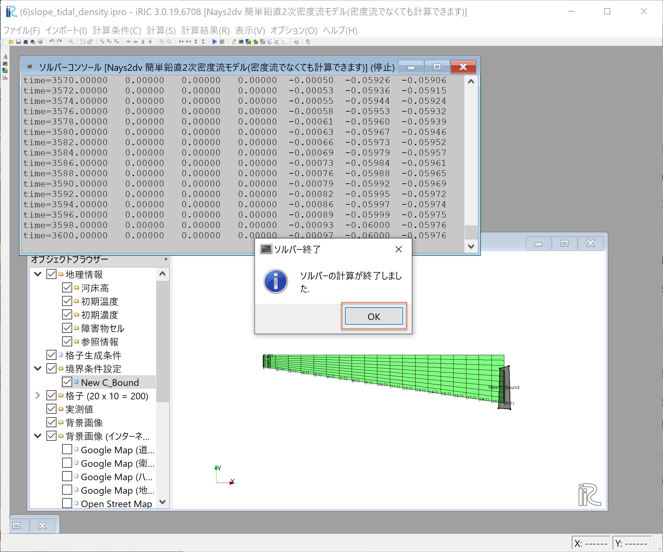
Figure 107 :計算の終了
計算が終了すると, Figure 107 のような表示がされるので,[OK]をクリックして 計算終了する.
計算結果の表示
ベクトルやスカラー量のコンター表示,水位等のグラフ表示は前章までの説明と同じなので ここでは結果のみ表示する.Figure 108 は(塩分)濃度コンターと流速ベクトルのア二メーション.
Figure 108 :流速ベクトルと濃度コンター表示
Figure 109 はベクトル・コンターと下流端水位変動を一緒に表示した動画 である.
Figure 109 :流速ベクトルと濃度コンター表示