Structure Culvert
Overview
Structure Culvert BC defines a culvert (pipe/box opening) through the wall of a Structure BC body. There are two types:
- Structure Culvert (i-direction): Culvert penetrating in the grid i-direction
- Structure Culvert (j-direction): Culvert penetrating in the grid j-direction
flowchart LR
    U["upstream"] -->|"  flow direction  "| STR
    subgraph STR["Structure body"]
        C["culvert opening"]
    end
    STR -->|"  flow direction  "| D["downstream"]
Prerequisites
Structure BC is required
A Structure BC must already be set at the same location before adding a Structure Culvert BC.
The culvert edge (grid line) must be placed on the boundary face of a Structure BC cell. Placing the culvert edge outside a Structure BC cell causes a runtime error.
Structure Culvert (i-direction)
For culverts penetrating in the grid i-direction (typically the main-flow direction).
Setup Procedure
Step 1: Add a Boundary Condition Group
Right-click Boundary Condition Setting in the left panel and select Structure Culvert (i-direction) to add a new group. It will appear as New Structure Culvert (i-direction) in the left panel (see screenshot on the previous page).
Step 2: Select the Culvert Edge
Select the new group and use the edge selection tool to pick a single i-direction grid edge on the structure wall face. The selected edge is highlighted in pink/magenta.
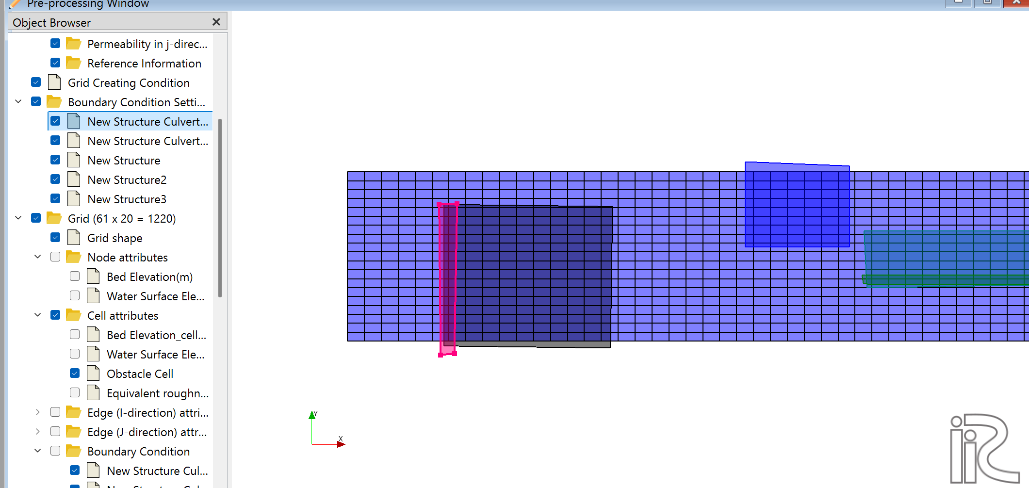
In the screenshot above, the culvert edge (pink) is selected on the left boundary face of the Structure body (dark area). The blue areas on the right are other Structure BC groups.
Edge placement
The selected edge must be a boundary face of a Structure BC cell. Selecting an edge outside the Structure body triggers an error at runtime.
Step 3: Set Culvert Parameters
| Parameter | Unit | Description |
|---|---|---|
| Vertical size of Culvert | m | Culvert height (vertical dimension) |
| Horizontal size of Culvert | m | Culvert width (horizontal dimension) |
| Invert elevation of Culvert | m | Absolute elevation of the culvert invert (bottom) |
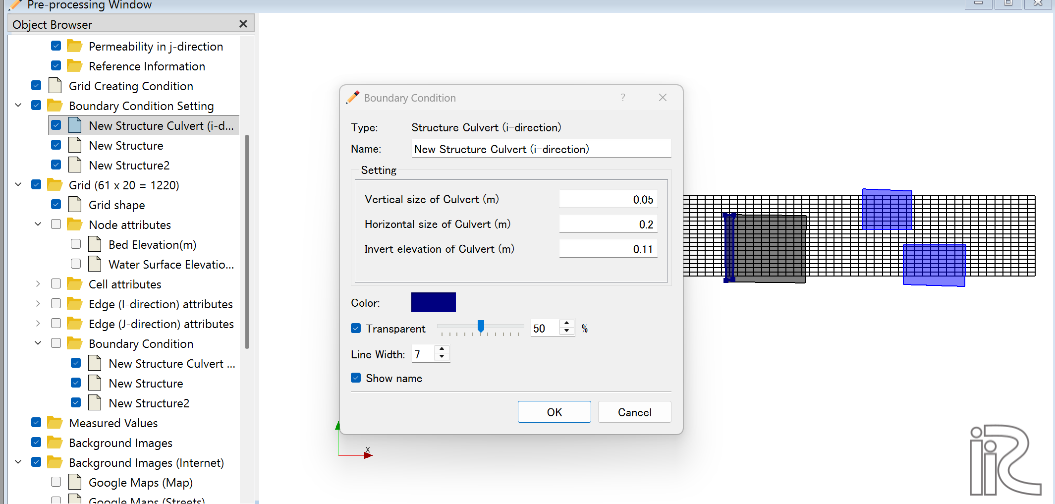
Example values shown: Vertical size = 0.05 m, Horizontal size = 0.2 m, Invert elevation = 0.11 m
Elevation relationships (top to bottom):
| Elevation (high → low) | Meaning |
|---|---|
| Water surface | Computed water level |
| Structure Top Elevation | Structure crest (Structure is solid below this) |
| Invert elevation + Vertical size | Culvert top |
| ↕ Vertical size | Height of culvert opening |
| Invert elevation | Culvert invert (bottom of opening) |
| eta | Riverbed elevation |
Step 4: Verify the Constraint
To ensure solid material exists above the culvert:
Required condition
Structure Top Elevation > Invert elevation + Vertical size
Correct example:
- Invert elevation = 0.100 m
- Vertical size = 0.300 m → Culvert top = 0.400 m
- Structure Top Elevation = 0.500 m ✓ (0.100 m of solid above culvert)
Incorrect example:
- Invert elevation = 0.100 m
- Vertical size = 0.300 m → Culvert top = 0.400 m
- Structure Top Elevation = 0.350 m ✗ (culvert extends beyond structure crest)
Structure Culvert (j-direction)
For culverts penetrating in the grid j-direction. The setup procedure is identical to i-direction.
In Boundary Conditions, select Structure Culvert (j-direction) and select a j-direction grid edge on the structure wall face.
Common Errors and Solutions
Error 1: Culvert face not on a Structure face
ERROR: Structure Culvert (i-direction) face at( i  j ) group N
       is not on a Structure face. Calculation stopped.
Cause: The selected culvert edge is not on the boundary face of a Structure BC cell.
Solution:
- In iRIC, check which cells have Structure BC assigned.
- Re-open the Structure Culvert BC settings and reselect the edge so it lies on a Structure cell boundary.
How to verify
Zoom in on the grid in the iRIC pre-processing view. Confirm that the culvert edge lies on the inner boundary face of the Structure BC cells (shown as blue highlights).
Issue: No solid above the culvert
No error is raised, but the culvert opening extends to or above the structure crest — no solid material remains above the culvert.
Diagnosis: Check the 3D view. If no solid structure is visible above the culvert opening, the crest elevation is too low.
Solution: Increase Structure Top Elevation to satisfy:
Structure Top Elevation > Invert elevation + Vertical size
Checking Results in Post-Processing
After the simulation, verify the following in the 3D post-processing view:
- Flow velocity vectors appear inside and downstream of the culvert opening
- Solid Structure material is present above the culvert
- Flow converges and passes through the culvert as expected
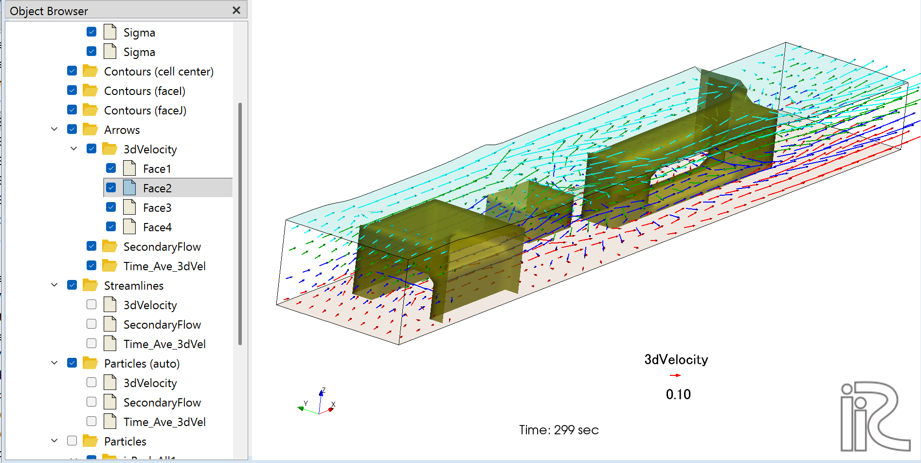
The screenshot above shows the steady-state result (299 sec) of the ijStructure test case. The upstream Structure has a culvert configured; flow passes through the culvert at the lower layers (red arrows) while overflowing the crest at upper layers (cyan arrows). The downstream Structure has overflow only (no culvert).