Structure BC
Overview
Structure BC is a boundary condition that blocks all σ-layers below a specified crest elevation, allowing flow only above that elevation. Use this feature to represent partial-height hydraulic structures such as weirs, sills, bed sills, and abutments in 3D.
You define the structure extent by drawing a polygon over the cells in plan view and assign a Structure Top Elevation parameter to each group.
Renamed from ThickWallBody
This feature was previously called ThickWallBody. The functionality is unchanged.
Obstacle Cell vs. Structure BC
→ See Obstacle Cell page for the comparison table.
Setup Procedure in iRIC
Step 1: Add a Boundary Condition Group
In the iRIC pre-processing screen, right-click Boundary Condition Setting in the left panel and select Structure to add a new group.
Step 2: Select Cells with a Polygon
Use the polygon tool to outline the plan-view footprint of the structure. Select all cells that form the structure body.
Multiple Structures
Create a separate Structure BC group for each independent structure.
Groups appear as New Structure, New Structure2, etc. in the left panel.
Each group can have a different Structure Top Elevation.
Step 3: Set Structure Top Elevation
Double-click the group in the left panel to open the Boundary Condition dialog. Enter the crest elevation in the Structure Top Elevation (m) field.
| Parameter | Unit | Description |
|---|---|---|
| Structure Top Elevation | m | Absolute elevation of the structure crest (use the same datum as the grid elevation data) |
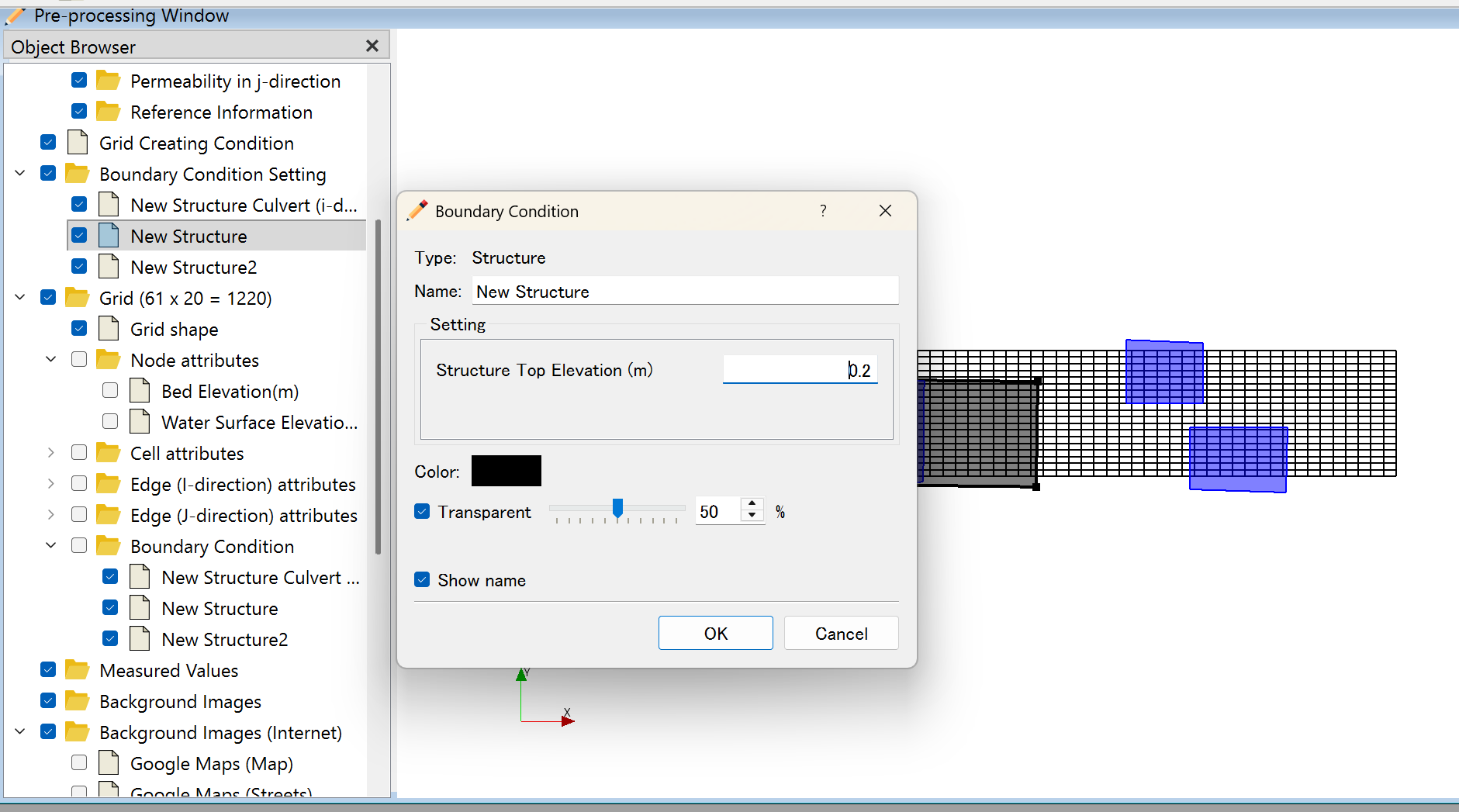
In the screenshot above, the left panel shows two groups (New Structure and New Structure2).
The dialog shows Structure Top Elevation (m) set to 0.2.
The blue-highlighted cells on the right side of the grid indicate the two Structure BC footprints.
Step 4: Verify in 3D View
Check the structure shape in 3D view before running the simulation.
- σ-layers with upper edge ≤ Structure Top Elevation → Solid (velocity = 0)
- σ-layers with upper edge > Structure Top Elevation → Fluid (velocity computed)
How It Works (σ-Coordinate System)
For each cell (i,j) and each vertical layer k, FreeBird evaluates:
Upper edge of σ-layer ≤ Structure Top Elevation  →  Solid layer
Upper edge of σ-layer >  Structure Top Elevation  →  Fluid layer
The Structure Top Elevation is a fixed value. As the water depth changes during simulation, the number of blocked layers remains constant (they are determined by absolute elevation, not by σ-fraction).
Using Structure Culvert with Structure BC
To add a culvert opening through the structure wall, set up a Structure Culvert BC in addition to the Structure BC.
Structure body .......... defined by Structure BC
  └── Culvert opening ... defined by Structure Culvert BC (additional)
Constraint when using Structure Culvert
When adding a culvert, the following condition must be satisfied:
Structure Top Elevation > Culvert Invert elevation + Culvert Vertical size
If this condition is not met, there will be no solid material above the culvert.
Notes
Elevation Datum
Enter Structure Top Elevation in the same coordinate system as the grid elevation data.
If the grid uses T.P. (Tokyo Peil), enter the T.P. elevation.
Group Independence
Each Structure BC group is processed independently. Adjacent groups can have different crest elevations.